This page explains the details of how the Loft surface is created. This is also relevant to Part Sweep done along a straight path, although there are differences.
The information provided is implementation specific, and may change. Current state is relevant to FreeCAD 0.15.4119, OCC version: 6.7.0.
Stages of the Loft creation
To explain the process of loft, it is convenient to divide it into stages:
- make number of segments in the profiles equal (if they are not already)
- establish correspondence between segments
- make the loft surface
Step 1. Making numbers of segment in profiles match
The Loft needs the number of segments to match in order to create surfaces between corresponding segments. If the numbers of segments match in all profiles, this step is skipped.
If at least one of the profiles has a different number of segments, the following procedure is applied. The procedure is explained here for the case of only two profiles for simplicity.
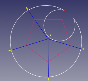
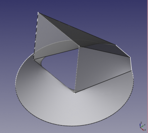
- the profiles are temporarily aligned so that they are coplanar and their centers of masses* match.
- (see the picture) for every vertex in one profile, the second profile is sliced at the same polar angle (the polar center is the center of mass). If there is more than one slice possible or no slice possible at all (it can happen on very convex profiles), the Loft typically fails.
- the same is done in the opposite direction.
The operation is extended to all profiles, to yield the equal number of segments. The total number of segments in each profile would be equal to the sum of all numbers of segments of all profiles (provided none of the vertices happen to be at the same polar angle).
 |
 |
Step 2. Establishing correspondence between segments
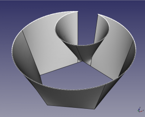
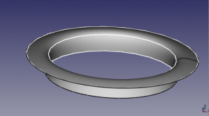
In case numbers of segments in all profiles were not equal, slicing was done in Step 1, and the correspondence is trivial. In case numbers of segments in all profiles were equal, existing segments are used (see the picture), and this is when the correspondence must be established.
The exact algorithm to find corresponding segments is complex, but generally it tends to minimize the twisting of the resulting Loft. This means that if one is doing a loft between two squares, the maximum twist possible is <45°. Further rotation of one of the squares will cause the Loft to jump to other vertices.
The correspondence between neighboring profiles is made independently. This means that additional twisting can be obtained by adding more profiles.
Another thing to note is that when numbers of segments in profiles are equal, the resulting Loft is substantially more robust with respect to complex profiles, especially for non-convex ones.
Step 3. Making the loft surface
If there are only two profiles, the surfaces created are ruled surfaces between corresponding segments of the profiles. Straight edges are created to connect corresponding vertices of the profiles.
If there are more than two profiles, the surfaces are made of splines in the same manner as straight lines form ruled surfaces. The imaginary splines the surface is "made of" are drawn through corresponding points of the corresponding segments of the profiles.
The splines are B-spline interpolation.
- If the number of profiles is below 10, interpolation is done with by a B-spline with a maximum possible degree (i.e. degree = number_of_profiles - 1).
- If the number of profiles exceeds 10, the interpolation is switched to 3rd degree B-splines.
The knotting method used is "approximate chord length". Approximate stands for the fact that the knot vector is exactly the same for every spline in a loft. For more info on what is B-spline interpolation, knot vector, chord length method, see, for example, cs.mtu.edu Curve Global Interpolation .
Note that Loft has a "Ruled" property. If it is set to true, ruled surfaces are made between neighboring profiles even when there's more than one profile. That is, B-spline interpolation is replaced by piecewise linear interpolation.
The main point
- The loft is doing B-spline interpolation between the provided profiles. The interpolation is switched to piecewise linear when "Ruled" property is set to true.
- When number of profiles exceeds 9, interpolation degree is dropped to 3. This switchover can substantially reduce wiggling.
- Matching the number of segments (aka number of vertices) in the profiles allows one to give the loft a slight twist, and typically permits using more complex profiles.
- When numbers of segments are not matched, it's best to keep the profiles to be representable by a proper r(phi) function in polar coordinates.
Additional remarks
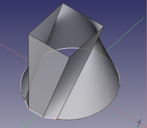
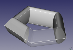
- It is not required that the profiles are parallel (see a picture below).
- For Loft, it is not required that the profiles are separated (see a picture below). They can be coplanar, but they should not intersect.
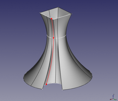
- When "closed" property of the Loft is "true", there is a cusp joint in all the splines forming the Loft (see a picture below). There is no reliable way to close the loft smoothly now.
 |
 |
 |
Эта страница получена от https://wiki.freecad.org/Part_Loft_Technical_Details