This documentation is not finished. Please help and contribute documentation.
GuiCommand model explains how commands should be documented. Browse Category:UnfinishedDocu to see more incomplete pages like this one. See Category:Command Reference for all commands.
See WikiPages to learn about editing the wiki pages, and go to Help FreeCAD to learn about other ways in which you can contribute.
|
|
| Menu location |
|---|
| Part Design → Substractive Features → Hole |
| Workbenches |
| PartDesign |
| Default shortcut |
| None |
| Introduced in version |
| 0.17 |
| See also |
| PartDesign Pocket |
Description
The Hole feature creates one or more holes from a selected sketch's circles and arcs. If arcs are present they must be part of closed contours. All non arc/circle entities are ignored but they still must form closed contours. Many parameters can be set such as threading and size, fit, hole type (countersink, counterbore, straight) and more.
The centers of the circles and arcs are used to position the holes, but please note that their radii are not taken into account. The generated holes will be identical even if the radii vary.
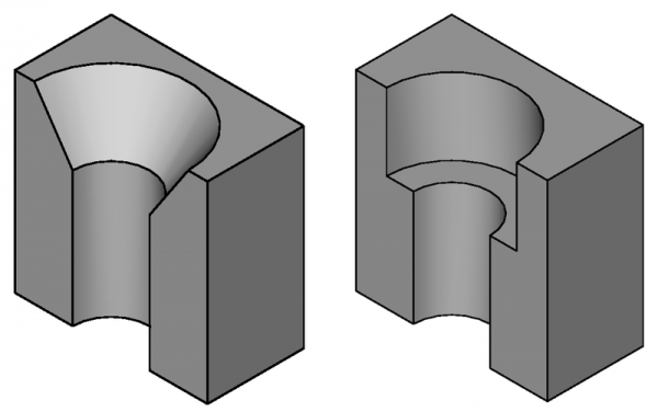
Cross-section of countersunk (on the left) and counterbored (on the right) holes.
Usage
- There are several ways to invoke the tool:
- Press the
 Hole button.
 - Select the Part Design → Subtractive Features → Hole option from the menu.
- Press the
- If an existing unused sketch is found, it will be used automatically. If more than one sketch is found, a Select Attachment panel appears to make a selection. Alternatively, a sketch can be selected before launching the Hole command.
- Define the Hole Parameters, that are described in section Options.
- Press OK.
Options
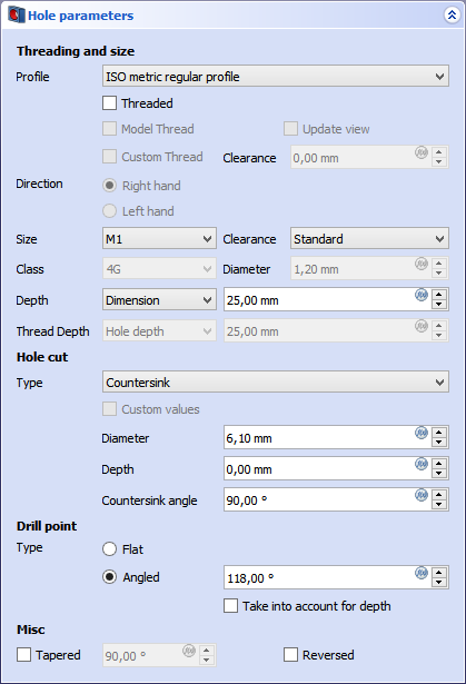
Depending on the specified options, some fields will be active or stay disabled.
- Profile:
- If set to None, no threading info is defined, and the diameter needs to be set manually.
- When set to a supported standard the diameter and other parameters can be set automatically.
- Threaded: Only available if Profile is not None
- If checked, the provided diameter will be the recommended drill size for post-processing with a cutting tap.
- If unchecked, the diameter is set according to Clearance to pass-through a thread without contact.
- Model Thread: Only available if threaded
- If checked a real thread is modeled. This consumes much computing power and is usually not used for models, except for display purposes or sometimes for 3D prints. If it is used, it is advised to check it as one of the last actions done to the model, because it will increase recomputation time significantly.
- Direction: Only available if threaded
- Sets the thread direction as Right Hand or Left hand.
- Size: Only available if threaded
- Sets the thread size. Requires Profile to not be None
- Clearance: Only available if non-threaded
- Determines the distance from the thread crest to the side of the hole. Can be understood as how tight a bolt will pass-through.
- For ISO threads the diameters are according to the ISO 273 standard
- For UTS they are calculated using a rule of thumb because there is no norm defining them.
- Class: Defines the tolerance class.
- Diameter: Defines the hole diameter, if the Profile is set to None.
- Depth: Depth of the hole from the sketch plane.
- Dimension: Enables a field to enter a value.
- Through All: Will cut the hole through the whole Body
- To reduce the file size, do not use Through All if Model Thread is checked, specify a minimal depth instead.
Hole cut
- Hole Cut Type: None means no cut, other types are the various norms for screws and the generic types Counterbore, Countersink and (introduced in 0.21) Counterdrill. ISO and DIN 7984 models appear if Profile receives an ISO or DIN selection.
- Diameter: sets the upper diameter (at the sketch plane) for the hole cut.
- Depth: The depth is defined differently depending on the Hole Cut Type:
- For a Counterbore, it is the depth of the hole cut, measured from the sketch plane.
- For a Countersink, it is the depth of the screw head top below the sketch plane.
- For a Counterdrill, it is the depth of the cylindrical part of the hole cut.
- Countersink angle: angle of the conical hole cut. Only applicable for countersinks, counterdrills, ISO 2009, ISO 7046, ISO 10642 profiles.
Drill point
- Drill point: defines the ending of the hole if Depth is set to Dimension.
- Flat produces a flat bottom
- Angled sets a conical point.
- Take into account for depth will subtract the conical height from the Dimension. So if for example Dimension is 7.00 and the option is not used, the cylindrical part of the hole will be 7.00 and the depth necessary for the conical part is added to the hole depth. If the option is used, the overall hole depth including the conical point will be 7.00.
Misc
- Tapered: sets a taper angle to the hole. Value is calculated from the sketch plane normal.
- 90 degrees sets a straight hole.
- Under 90 generates a smaller hole radius at the end, larger at the start.
- Over 90 generates a larger hole radius at the end, smaller at the start.
- Reversed: reverses the hole extrusion direction. The default direction is the mapping direction of the hole sketch to its attachment.
Properties
Much of the Data properties are the same as those shown in Options.
- DataLabel: name given to the object, this name can be changed at convenience.
- DataRefine: true or false. If set to true, cleans the solid from residual edges left by features. See
 Part RefineShape for more details.
Limitations
- By default, the hole feature extrudes below the sketch plane. If the solid lies on the XY_Plane, and the hole sketch is attached to the XY_Plane, it will try to extrude away from the solid and seemingly produce no result. In such a case, the option Reversed needs to be set; alternatively the sketch can be mapped to the bottom face of the solid.
Cut Type Definitions
Cut types (screw-types) are defined in json files. There is a set of files distributed with FreeCAD, but users can create their own definitions. Files are searched in <UserAppDataDir>/PartDesign/Hole. The UserAppDataDir can be found by typing App.getUserAppDataDir() in the Python Console.
The file should contain:
- name: The name of the definition. This must be unique as it will be used as identifier in the FreeCAD UI and as internal index.
- cut_type: Either
countersinkorcounterbore. - thread_type: Either
metricormetricfine. - angle: The angle of a countersink (not necessary for counterbore).
- data: A list of sizes, consisting of:
- thread: Name of thread known to FreeCAD.
- diameter: The diameter of the cut.
- depth: Depth of the counterbore (not necessary for countersink).
Example:
{
    "name": "DIN 7984",
    "cut_type": "counterbore",
    "thread_type": "metric",
    "data": [
        { "thread": "M2",   "diameter":  4.3, "depth":  1.6 },
        { "thread": "M2.5", "diameter":  5.0, "depth":  2.0 },
        …
    ]
}
This page is retrieved from https://wiki.freecad.org/PartDesign_Hole