|
|
| Opis |
|---|
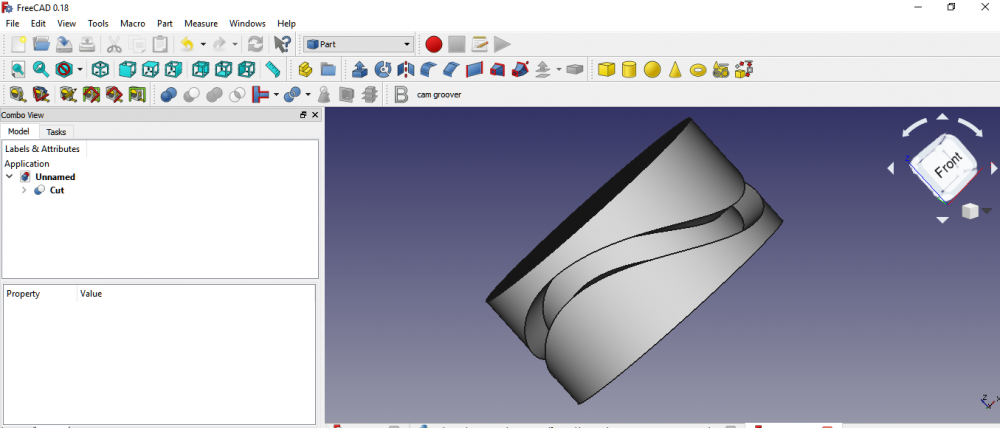
| To makro tworzy rowek w cylindrze, po którym porusza się krzywka. Utworzony obiekt jest podobny do tego przedstawionego w tym filmie na youtube. Macro version: 2020.06.13 Last modified: 2020.06.13 FreeCAD version: 0.19 i nowszy Download: Ikona paska narzędzi Autor: TheMarkster |
| Autor |
| TheMarkster |
| Do pobrania |
| Ikona paska narzędzi |
| Odnośniki |
| Przepisy na makropolecenia Jak zainstalować makrodefinicje Dostosowanie pasków narzędzi |
| Wersja Makrodefinicji |
| 2020.06.13 |
| Data zmian |
| 2020.06.13 |
| Wersja FreeCAD |
| 0.19 i nowszy |
| Domyślny skrót |
| Brak |
| Zobacz również |
| - |
Opis
To makro tworzy rowek w cylindrze, po którym porusza się krzywka.
Utworzony obiekt jest podobny do tego przedstawionego w tym filmie na youtube.
Skrypt
Ikonka paska narzędzi ![]()
Macro_FCCamGroover.FCMacro
# -*- coding: utf-8 -*-
import FreeCAD
from FreeCAD import Base
from PySide import QtGui,QtCore
import Part, Draft
from math import *
import time
import math


__title__ = "FC Cam Groover"
__author__ = "TheMarkster"
__url__ = "https://wiki.freecad.org/Macro_FCCamGroover"
__Wiki__ ="https://wiki.freecad.org/Macro_FCCamGroover"
__date__ = "2020.06.13"
__version__ = __date__

msg = u"""FC Cam Groover v"""+__version__+""", a macro to create a cam groove in a cylinder, Copyright (c) 2018 by 'TheMarkster'<br/>
<br/>
Credit to Gomez Lucio and Laurent Despeyroux for their macro, '3D Parametric Curve Macro', 2015, which provided inspiration
for some of the code used herin.  Thanks also to emills2 for his invaluable feedback. All errors are mine, not theirs.<br/>
<br/>
The grooved cylinder produced will be similar to the one depicted in this video: <a href = 'https://youtu.be/io1JL1U7kUs'>https://youtu.be/io1JL1U7kUs</a><br/>
<br/>
Parameters supported: cylinder height, cylinder radius, groove depth, groove width, strokes per revolution, stroke range, steps (precision) <br/>
<br/>
This file is a supplement to the FreeCAD CAx development system.
<br/>
This program is free software; you can redistribute it and/or modify
it under the terms of the GNU Lesser General Public License (LGPL)
as published by the Free Software Foundation; either version 2 of
the License, or (at your option) any later version.
<br/>
<br/>
This software is distributed in the hope that it will be useful,
but WITHOUT ANY WARRANTY; without even the implied warranty of
MERCHANTABILITY or FITNESS FOR A PARTICULAR PURPOSE.  See the
GNU Library General Public License at <a href='http://www.gnu.org/licenses'>http://www.gnu.org/licenses</a>
for more details.<br/>
<br/>
For more information about the GNU Library General Public License
write to the Free Software Foundation, Inc., 59 Temple Place,
Suite 330, Boston, MA  02111-1307 USA
<br/>
"""
title = u"""Welcome to FC Cam Groover Macro"""
icon=QtGui.QMessageBox.Information
diag = QtGui.QMessageBox(icon, title, msg)
diag.setWindowModality(QtCore.Qt.ApplicationModal)
diag.setTextFormat(QtCore.Qt.RichText);
diag.exec_()

window = QtGui.QMainWindow()

def say(msg):
    FreeCAD.Console.PrintMessage(msg);

def processEvents():
     time.sleep(0.001)
     QtGui.QApplication.processEvents()

def getDouble(txt1,txt2,default,start=0,decimals=4):
    inp,ok = QtGui.QInputDialog.getDouble(window, txt1,txt2,default, start,1000000, decimals)
    if ok:
        return inp
    else:
        raise StandardError('User canceled')

def getInt(txt1,txt2,default):
    inp, ok = QtGui.QInputDialog.getInt(window, txt1,txt2,default, 1, 100000, 1)
    if ok:
        return inp
    else:
        raise StandardError('User canceled')


def getDistance3d(x1, y1, z1, x2, y2, z2):
    return math.sqrt((x1 - x2)**2 + (y1 - y2)**2 + (z1 - z2)**2)

radius = getDouble(u'Radius of Cylinder',u'Enter radius of cylinder (in mm).\nMake sure it\'s big enough or the operation will fail:',10)
cylinderHeight = getDouble(u'Height of Cylinder', u'Enter the height of the cylinder. (in mm)\n(Can be adjusted after the macro finishes.)',10)
depth = getDouble(u'Depth of Groove', u'Enter the depth of the groove to be cut into the cylinder (in mm):',2)
slotHeight = getDouble(u'Height of Groove',u'Enter the height of the slot to be cut into the cylinder.\n\nNote: this is not the stroke length, which will be input below. (in mm) ',2)
innerRadius = radius-depth
strokeFactor = getDouble(u'Stroke Length',u'Enter the axial length of the stroke: (in mm)',5)
strokeFactor /= radius
strokesPerRevolution = getInt(u'Strokes per Revolution',u'Enter the number of strokes per revolution of the cylinder.\n1 or 2 seems to work okay, but anything beyond 3 could be troublesome:', 2)
steps = getInt(u'Steps',u'Enter number of steps (points) in curve, the more points the more precise the curve,\nbut the longer to process.  If it\'s too small the operation *will* fail.\nExperiment with this value if you are having trouble with a particular groove.\nThe default is 628:',628)

#inspiration for this makeBSpline function is from the 3d parametric curve macro
#it is not an exact copy/paste of the code, but rather is based on the same principles
#but without overhead of the gui


def makeBSpline(strokesPerRevolution,strokeFactor,radius,steps):
    a = strokesPerRevolution
    b = strokeFactor
    c = radius
    interval = (2*math.pi)/float(steps)
    points=[]
    t = 0.0
    maxT = 2*math.pi
    counter=0
    while t <= maxT:
        say(u'Step '+str(counter)+u' of '+str(steps)+u'\n')
        counter +=1
        processEvents()
        x = math.cos(t)*c
        y = math.sin(t)*c
        z = math.sin(t*a/2.0)*math.cos(t*a/2.0)*c*b
        points.append(App.Vector(x,y,z))
        t += interval

    Draft.makeBSpline(points,closed=True,face=False)
    say(u'Done with BSpline\n')
    processEvents()


if not App.ActiveDocument:
    App.newDocument()
toBeRemoved=[] #temporary objects to be removed to clean up tree
say(u'Making BSpline...\n')
processEvents()
makeBSpline(strokesPerRevolution,strokeFactor,radius,steps)
App.ActiveDocument.recompute()
bs = App.ActiveDocument.ActiveObject


#we use an array of circles aligned along the bspline to create a new
#bspline that closely follows (but is not exact copy of) original bspline
#each circle has a vertex, similar to the seam line of a cylinder
#these vertices are used to create a list of points from which the new
#bspline is created
#simply moving the original bspline along the z axis does not work because
#the groove will narrow in places and widen in others.  the circles ensure
#better (though probably still not perfect) uniformity of the groove


Draft.makeCircle(slotHeight,face=False)
cir = App.ActiveDocument.getObject('Circle')
cir.Placement=App.Placement(App.Vector(0,0,0), App.Rotation(90,0,0), App.Vector(0,0,0))
App.ActiveDocument.recompute()
say(u'Making a draft path array of '+str(steps)+' circles, waiting for FreeCAD...\n')
processEvents()
try:
    Draft.make_path_array(cir,bs,count=steps,align=True,align_mode='Tangent',tan_vector=App.Vector(0,0,1),force_vertical=True)
except:
    title = u"""Potential incompatibility with this version of FreeCAD"""
    msg='There is a potential incompatibility with this version of FreeCAD.  If the groove does not appear correct after processing completes \
update to version 0.19 or later and try again.'
    icon=QtGui.QMessageBox.Information
    diag = QtGui.QMessageBox(icon, title, msg)
    diag.setWindowModality(QtCore.Qt.ApplicationModal)
    diag.setTextFormat(QtCore.Qt.RichText);
    diag.exec_()
    Draft.makePathArray(cir,bs,count=steps,xlate=None,align=True)
App.ActiveDocument.recompute()
pa = App.ActiveDocument.getObject('PathArray')
points = []
for v in pa.Shape.Vertexes:
    points.append(v.Point)
Draft.makeBSpline(points,True,None)
bs1 = App.ActiveDocument.ActiveObject
App.ActiveDocument.recompute()

say(u'Scaling bspline1...\n')
processEvents()
Draft.scale([bs],FreeCAD.Vector(innerRadius/float(radius),innerRadius/float(radius),1.0),center=FreeCAD.Vector(0.0,0.0,0.0),copy=True)
bs2 = App.ActiveDocument.ActiveObject
say(u'Scaling bspline2...\n')
processEvents()
Draft.scale([bs1],FreeCAD.Vector(innerRadius/float(radius),innerRadius/float(radius),1.0),center=FreeCAD.Vector(0.0,0.0,0.0),copy=True)
bs3 = App.ActiveDocument.ActiveObject
#now make the original bsplines bigger so they extend outside the cylinder edges (to prevent issues with boolean cut later on)
Draft.scale([bs],FreeCAD.Vector(1.05,1.05,1.0),center=FreeCAD.Vector(0.0,0.0,0.0),copy=False)
say(u'Scaling bspline2...\n')
processEvents()
Draft.scale([bs1],FreeCAD.Vector(1.05,1.05,1.0),center=FreeCAD.Vector(0.0,0.0,0.0),copy=False)
say(u'Making ruled surfaces.')
processEvents()
FreeCAD.ActiveDocument.addObject('Part::RuledSurface', 'Ruled Surface')
FreeCAD.ActiveDocument.ActiveObject.Curve1=(bs1,['Edge1'])
FreeCAD.ActiveDocument.ActiveObject.Curve2=(bs3,['Edge1'])
FreeCAD.ActiveDocument.ActiveObject.Orientation = u"Forward"
rs = FreeCAD.ActiveDocument.ActiveObject
say(u'.')
processEvents()
FreeCAD.ActiveDocument.addObject('Part::RuledSurface', 'Ruled Surface')
FreeCAD.ActiveDocument.ActiveObject.Curve1=(bs2,['Edge1'])
FreeCAD.ActiveDocument.ActiveObject.Curve2=(bs3,['Edge1'])
FreeCAD.ActiveDocument.ActiveObject.Orientation=u"Forward"
rs1 = FreeCAD.ActiveDocument.ActiveObject
say(u'.')
processEvents()
FreeCAD.ActiveDocument.addObject('Part::RuledSurface', 'Ruled Surface')
FreeCAD.ActiveDocument.ActiveObject.Curve1=(bs1,['Edge1'])
FreeCAD.ActiveDocument.ActiveObject.Curve2=(bs,['Edge1'])
FreeCAD.ActiveDocument.ActiveObject.Orientation=u"Forward"
rs2 = FreeCAD.ActiveDocument.ActiveObject
say(u'.')
processEvents()
FreeCAD.ActiveDocument.addObject('Part::RuledSurface', 'Ruled Surface')
FreeCAD.ActiveDocument.ActiveObject.Curve1=(bs2,['Edge1'])
FreeCAD.ActiveDocument.ActiveObject.Curve2=(bs,['Edge1'])
FreeCAD.ActiveDocument.ActiveObject.Orientation = u"Forward"
rs3 = FreeCAD.ActiveDocument.ActiveObject
say(u'. Done.\n')
processEvents()

toBeRemoved.extend([bs.Name,bs1.Name,bs2.Name,bs3.Name,rs.Name,rs1.Name,rs2.Name,rs3.Name,pa.Name,cir.Name])

App.ActiveDocument.recompute()

say(u'Building shell...\n')
processEvents()
try:
    _=Part.Shell([App.ActiveDocument.getObject(rs3.Name).Shape.Faces[0], App.ActiveDocument.getObject(rs2.Name).Shape.Faces[0], App.ActiveDocument.getObject(rs.Name).Shape.Faces[0], App.ActiveDocument.getObject(rs1.Name).Shape.Faces[0], ])
except:
    say('Exception making shell.  You might try increasing the number of steps, which sometimes helps.\n')
    raise StandardError('Exception creating shell object.')
if _.isNull(): raise RuntimeError('Failed to create shell')
App.ActiveDocument.addObject('Part::Feature','Shell').Shape=_.removeSplitter()
del _
shell = App.ActiveDocument.ActiveObject
toBeRemoved.extend([shell.Name])


App.ActiveDocument.recompute()

say(u'Making shell into a solid...\n')
processEvents()

__s__=App.ActiveDocument.Shell.Shape
__s__=Part.Solid(__s__)
__o__=App.ActiveDocument.addObject("Part::Feature","GrooveFeature")
__o__.Label="GrooveFeature"
__o__.Shape=__s__
del __s__, __o__
shellSolid = App.ActiveDocument.ActiveObject
App.ActiveDocument.recompute()

say('Building cylinder...\n')
processEvents()
App.ActiveDocument.addObject("Part::Cylinder","Cylinder")
App.ActiveDocument.ActiveObject.Label = "Cylinder"
App.ActiveDocument.getObject("Cylinder").Radius = str(radius)
App.ActiveDocument.getObject("Cylinder").Height = str(cylinderHeight)
cylinder = App.ActiveDocument.ActiveObject


shellSolid.Placement=App.Placement(App.Vector(0,0,-slotHeight/2.0), App.Rotation(0,0,0), App.Vector(0,0,0)) #center groove in cylinder
cylinder.Placement=App.Placement(App.Vector(0,0,-cylinderHeight/2.0), App.Rotation(10,0,0), App.Vector(0,0,0)) #rotate slightly to move the edge lines apart

App.ActiveDocument.recompute()

say(u'Cleaning up temporary objects.')
processEvents()
for tbr in toBeRemoved:
    App.ActiveDocument.removeObject(tbr)
    say(u'.')
    processEvents()
say(u'. Done.\n')

App.ActiveDocument.recompute()
Gui.SendMsgToActiveView("ViewFit")

msg=u"""
Done.  Last thing you need to do is the boolean cut from the Part workbench, cutting Groove Feature from the cylinder,
if all looks good.  It is recommended to check the geometry via the Part workbench menu with RunBoPCheck = True enabled
in Tools -> Edit Parameters -> Preferences -> Mod -> Part -> CheckGeometry.  If the check fails, go back and do it again
with a different number of steps.  Sometimes it might be necessary to adjust the z-position Placement of the Groove Feature.
"""
title=u'Thanks for using FC Cam Groover'
icon=QtGui.QMessageBox.Information
diag = QtGui.QMessageBox(icon, title, msg)
diag.setWindowModality(QtCore.Qt.ApplicationModal)
diag.setTextFormat(QtCore.Qt.RichText);
diag.exec_()
Łącze
Forum FC Cam Groover Macro
Ta strona pochodzi z https://wiki.freecad.org/Macro_FCCamGroover