TechDraw Preferences
Introduction
The preferences for the  TechDraw Workbench can be found in the Preferences Editor. In the menu select Edit → Preferences... and then TechDraw. This group is only available if the TechDraw Workbench has been loaded in the current FreeCAD session.
There are seven pages: General, Scale, Dimensions, Annotation, Colors, HLR and Advanced.
All preferences with italic labels are default values for new drawing objects. They have no effect on existing objects.
This page has been updated for version 1.0.
General
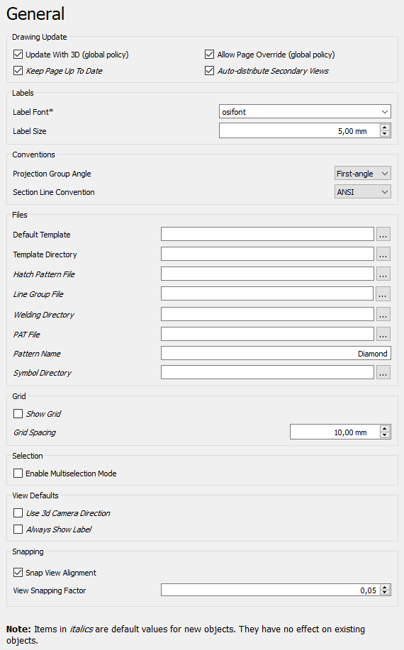
Drawing Update
- Update With 3D (global policy): Whether or not pages are updated every time the 3D model is changed.
- Allow Page Override (global policy): Whether or not a page\'s Keep Updated property can override the global Update With 3D parameter.
- Keep Page Up To Date: Keeps drawing pages in sync with changes of the 3D model in real time. This can slow down the response time.
- Auto-distribute Secondary Views: Automatically distributes secondary views for projection groups.
Labels
- Label Font: The name of the font for labels. The font is also used for new dimensions, changing it has no effect on existing dimensions.
- Label Size: Default size for labels.
Conventions
- Projection Group Angle: If projection groups will use either first-angle (European) projection or third-angle (American) projection. See multiview projection for an explanation.
- Section Line Convention: Standard for section lines that controls the position of arrows and symbol ((v1.0) ). The options are:
- ANSI
- ISO
Files
- Default Template: Default template file for new pages.
- Template Directory: Starting directory for toolbar button
 Insert Page using Template.
 - Hatch Pattern File: Default SVG or bitmap file for hatches.
- Line Group File: Alternate file for personal line group definitions.
- Welding Directory: Default directory for toolbar button [
 Add Welding Information to Leader.
 - PAT File: Default PAT pattern definition file for geometric hatches.
- Pattern Name: Name of the default PAT pattern.
- Symbol Directory: Alternate directory to search for SVG symbol files.
Grid
- Show Grid: Default Show Grid setting for new pages.
- Grid Spacing: Default distance between grid lines for new pages.
Selection
- Enable Multiselection Mode: If enabled, clicking without Ctrl does not clear the existing selection. (v1.0)
View Defaults
- Use 3d Camera Direction: If checked, the 3d camera direction (or normal of a selected face) will be used as the view direction. If not checked, Views will be created as Front Views. (v1.0)
- Always Show Label: If checked, view labels will be displayed even when frames are suppressed. (v1.0)
Snapping
- Snap View Alignment: If checked, Views will be snapped into alignment when dragged. (v1.0)
- View Snapping Factor: Tolerance for snapping of Views - if a View is within this fraction of View size of perfect alignment, it will snap into alignment. (v1.0)
Scale
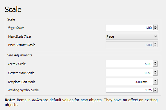
Scale
- Page Scale: Default scale for new pages.
- View Scale Type: Default scale for new views.
- View Custom Scale: Default scale for views if View Scale Type is Custom.
Size Adjustments
- Vertex Scale: Scale of vertex dots. Multiplier of line width.
- Center Mark Scale: Size of center marks. Multiplier of vertex size.
- Template Edit Mark: Size of template field click handles in mm (green dots).
- Welding Symbol Scale: Multiplier for size of welding symbols.
Dimensions
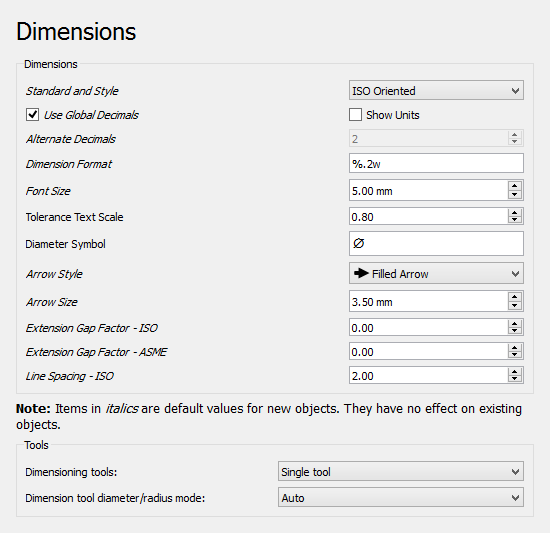
Dimensions
- Standard and Style: The standard to be used for dimensional values. The differences between the standards are shown in the image: <img alt="Differences between the supported standards. ([Image source" src=https://raw.githubusercontent.com/FreeCAD/FreeCAD-documentation/master/wiki/images/https://forum.freecadweb.org/viewtopic.php?f=35&t=39571#p336144))](TechDraw_Dimension_standardization.png style="width:500px;">
)](TechDraw_Dimension_standardization.png)
:
:   ISO Oriented - drawn according to the standard ISO 129-1, text is rotated to be parallel with the dimension line tangent.
:   ISO Referencing - drawn in compliance with ISO 129-1, text is always horizontal, above the shortest possible reference line.
:   ASME Inlined - drawn according to the standard ASME Y14.5M, text is horizontal, inserted in a break within the dimension line or arc.
: ASME Referencing - drawn in compliance with ASME Y14.5M, text is horizontal, short reference line is attached to one side\'s vertical center.- Use Global Decimals: Use number of decimals from the general preferences.
- Show Units: Appends the unit (mm, in, etc.) to dimension values.
- Alternate Decimals: Number of decimals if Use Global Decimals is not selected and Dimension Format not specified.
- Dimension Format: Custom format for dimension text. Uses the printf format specifier.
- Font Size: Font size for dimension text.
- Tolerance Text Scale: Tolerance font size adjustment. Multiplier of dimension Font Size.
- Diameter Symbol: Character used to indicate diameter dimensions.
- Arrow Style: Arrowhead style for dimensions.
- Arrow Size: Arrowhead size of dimensions.
- Extension Gap Factor - ISO: Gap between dimension point and start of extension lines for ISO dimensions. (v0.21)
- Extension Gap Factor - ASME: Gap between dimension point and start of extension lines for ASME dimensions. (v0.21)
- Line Spacing - ISO: Spacing between the dimension line and dimension text for ISO dimensions. (v0.21)
Tools
- Dimensioning tools: Select the type of dimensioning tools for the toolbar. Whichever you choose, all tools are always available in the menu and through shortcuts. The options are: (v1.0)
- Single tool: A single tool for all dimensioning in the toolbar: Distance, Distance X / Y, Angle, Radius. Others in dropdown.
- Separated tools: Individual tools for each dimensioning tool.
- Both: You will have both the \'Single tool\' and the separated tools.
- Dimension tool diameter/radius mode: While using the Dimension tool you may choose how to handle circles and arcs: (v1.0)
- Auto: The tool will apply radius to arcs and diameter to circles.
- Diameter: The tool will apply diameter to all.
- Radius: The tool will apply radius to all.
Annotation
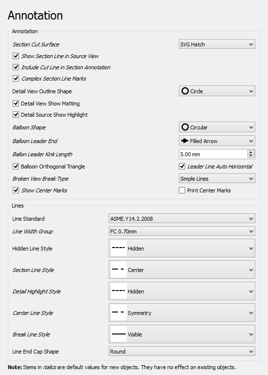
Annotation
- Section Cut Surface: Style for section cut surface. The options are:
- Hide: There is no visible surface.
- Solid Color: The surface gets the color set for Section Face
- SVG Hatch: The surface is hatched.
- PAT Hatch: The surface is geometrically hatched.
- Show Section Line in Source View: If checked, the section annotation will be drawn on the Source view. If unchecked, no section line, arrows or symbol will be shown in the Source view. (v1.0)
- Include Cut Line in Section Annotation: If checked, the cut line will be drawn on the Source view. If unchecked, only the change marks, arrows and symbols will be displayed. (v1.0)
- Complex Section Line Marks: Show marks at direction changes on ComplexSection lines. (v0.21)
- Detail View Outline Shape: Outline shape for detail views. The options are:
- Circle
- Square
- Detail View Show Matting: This checkbox controls whether or not to display the outline around a detail view. (v1.0)
- Detail Source Show Highlight: This checkbox controls whether or not to display a highlight around the detail area in the detail\'s source view. (v1.0)
- Balloon Shape: Shape of balloon annotations.
- Balloon Leader End: Default style for balloon leader line ends, see balloon properties.
- Balloon Leader Kink Length: Length of balloon leader line kink.
- Balloon Orthogonal Triangle: If Balloon Leader End is Filled Triangle, the triangle can only get a vertical or horizontal direction when the balloon is moved.
- Leader Line Auto Horizontal: Forces last leader line segment to be horizontal.
- Broken View Break Type: Default break type used to indicate BrokenViews: (v1.0)
- No Break Lines
- ZigZag Lines
- Simple Lines
- Show Center Marks: Show arc center marks in views.
- Print Center Marks: Show arc centers in printed output.
Lines
- Line Standard: Standard to be used to draw section lines in section views.
- Line Width Group: A LineGroup to set the default line widths.
- Hidden Line Style: Style of hidden lines. (v1.0)
- Section Line Style: Style for section lines.
- Detail Highlight Style: Line style of the outline shape for detail views.
- Center Line Style: Default style for centerlines.
- Break Line Style: Default style for lines used to indicate BrokenViews. (v1.0)
- Line End Cap Shape: The default (round) should almost always be the right choice. Flat or square caps are useful if you are planning to use a drawing as a 1:1 cutting guide.
Colors
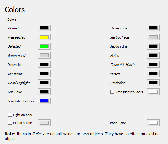
Setup of the default colors for new pages:
- Normal: Normal line color.
- Preselected: Preselection color. The color that is used to highlight objects when hovering with the mouse over them.
- Selected: Color for selected objects.
- Background: Background color around pages.
- Dimension: Color of dimension lines and text.
- Centerline: Color for centerlines.
- Detail Highlight: Line color for the outline shape of detail views.
- Grid Color: Color for all page grids.
- Template Underline: Color for the underline that marks editable texts in templates. (v1.0)
- Hidden Line: Hidden line color. This color will be used for all kinds of hidden lines.
- Section Face: Color of the section view cut surface. Only used if the setting Section Cut Surface is set to Solid Color.
- Section Line: Color of the section view cut line.
- Hatch: Hatch image color.
- Geometric Hatch: Geometric hatch pattern color.
- Vertex: Color of the selectable vertices in views.
- Leaderline: Color for new leaderlines.
- Transparent Faces: If checked, object faces will be transparent. Otherwise the set color will be used for faces.
- Light on dark: If checked text and lines will have a light color. To be used if the Page Color is dark. Transparent or light colored faces are recommended with this option. (v0.21)
- Monochrome: If checked, the set color will be used for all text and lines. (v0.21)
- Page Color: The background color of the page. (v0.21)
HLR
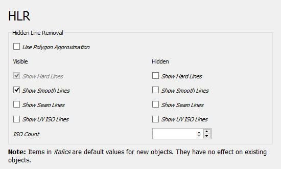
HLR stands for hidden line removal.
- Use Polygon Approximation: Uses an approximation to find hidden lines. This is fast, but the result is a collection of short straight lines.
- Show Hard Lines: Shows hard and outline edges (visible lines always shown)
- Show Smooth Lines: Shows smooth lines. A smooth line is a line indicating a change between tangent surfaces, as in the transition from a flat surface to a fillet.
- Show Seam Lines: Show seam lines. A seam line is a boundary between faces.
- Show UV ISO Lines: Shows ISO lines. ISO stands for isoparametric. Here is a description what isoparametric lines (in fact curves) are.
- ISO Count: The number of ISO lines per face edge.
Advanced
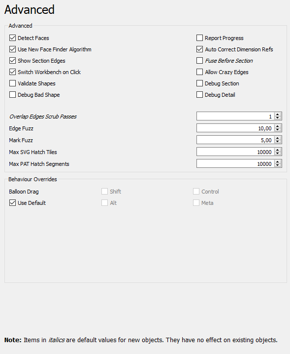
- Detect Faces: If checked, TechDraw will attempt to build faces using the line segments returned by the hidden line removal algorithm. Faces must be detected in order to use hatching, but there can be a performance penalty in complex models.
- Report Progress: Issue progress messages while building View geometry. (v0.21)
- Use New Face Finder Algorithm: If checked, the new face finder algorithm will be used instead of the original one. (v0.21)
- Auto Correct Dimension Refs: If checked, an attempt is made to update dimension references when the model changes. (v0.21)
- Show Section Edges: Highlights the border of the section cut in section views.
- Fuse Before Section: Performs a fuse operation on the input shape(s) before Section view processing.
- Switch Workbench on Click: If checked, double-clicking on a page in the tree will automatically switch to TechDraw and the page will be made visible. (v1.1)
- Allow Crazy Edges: Includes edges with unexpected geometry in results, e.g. zero lengths.
- Validate Shapes: If checked, input shapes will be checked for errors before use and invalid shapes will be skipped. It can be slower but may prevent crashes. (v1.1)
- Debug Section: Dumps intermediate results during a Section view processing.
- Debug Bad Shape: If checked, shapes that failed validation will be saved as B-rep files for later analysis. (v1.1)
- Debug Detail: Dumps intermediate results during a Detail view processing.
- Overlap Edges Scrub Passes: The number of attempts to remove overlapping edges returned by the Hidden Line Removal algorithm. A value of 0 indicates no scrubbing. Values above 2 are generally not productive. Each attempt adds to the time required to produce the drawing. (v0.21)
- Edge Fuzz: Size of selection area around edges. The fuzz unit is approximately 0.1 mm, depending on your current zoom. The default is 10. Values in the 20-30 range will make it noticeably easier to select edges. Large numbers will cause overlaps with other drawing elements.
- Mark Fuzz: Selection area around center marks. The fuzz unit is approximately 0.1 mm, depending on your current zoom.
- Max SVG Hatch Tiles: The limit of SVG tiles with a size of 64x64 pixels used to hatch a single face. For large scalings one might get an error about to many SVG tiles, then one needs to increase the tile limit.
- Max PAT Hatch Segments: The maximum hatch line segments used when hatching a face with a PAT pattern.
- Balloon Drag: Modifier key for balloon drag can be changed from the default here to avoid conflicts with OS or navigation style key bindings. (v1.0)
{{TechDraw Tools navi}}
⏵ documentation index > Preferences > TechDraw > TechDraw Preferences
This page is retrieved from https://github.com/FreeCAD/FreeCAD-documentation/blob/main/wiki/TechDraw_Preferences.md