TutorialInfo: Topic: Scripting Level: Base Time: Author: onekk Carlo FCVersion: 0.19 Files:
Scripts
Introduction
With Scripting we mean create topological objects using FreeCAD\'s Python interpreter. FreeCAD could be used as a \"very good\" replacement of OpenSCAD, mainly because it has a real Python interpreter, that means that it has a real programming language on board, almost everything you could do with the GUI, is doable with a Python Script.
Sadly information about scripting in the documentation, and even in this wiki are scattered around and lacks of \"writing\" uniformity and most of them are explained in a too technical manner.
Getting started
The first obstacle in an easy way to scripting is that there is no direct way to access the FreeCAD internal Python editor through a menu item or a icon on the toolbar area, but knowing that FreeCAD opens a file with a .py extension in the internal Python editor, the most simple trick is create in your favorite text editor and then open it with the usual command File → Open.
To make the things in a polite way, the file has to be written with some order, FreeCAD Python editor have a good \"Syntax Highlighting\" that lacks in many simple editors like Windows Notepad or some basic Linux editors, so it is sufficient to write these few lines:
"""filename.py

   A short description of what the script does

"""
Save them with a meaningfull name with .py extension and load the resulting file in FreeCAD, with the said File → Open command.
A minimal example of what is necessary to have in a script is shown in this portion of code that you could be use as a template for almost any future script:
"""filename.py

   First FreeCAD Script

"""

import FreeCAD
from FreeCAD import Placement, Rotation, Vector
import FreeCADGui

DOC_NAME = "Wiki_Example"
DOC = FreeCAD.newDocument(DOC_NAME)
FreeCAD.setActiveDocument(DOC.Name)

ROT0 = Rotation(0, 0, 0)
VEC0 = Vector(0, 0, 0)

# Helper function

def set_view():
    """Rearrange View."""
    if not FreeCAD.GuiUp:
        return
    doc = FreeCADGui.ActiveDocument
    if doc is None:
        return
    view = doc.ActiveView
    if view is None:
        return
    # Check if the view is a 3D view:
    if not hasattr(view, "getSceneGraph"):
        return
    view.viewAxometric()
    view.fitAll()
Some tricks are incorporated in the above code:
-
import FreeCADThis line import FreeCAD in the FreeCAD Python interpreter, it may seem a redundant thing, but it isn\'t. -
from FreeCAD import Placement, Rotation, VectorPlacement Rotation and Vector are widely used in FreeCAD scripting, import them in this manner will save you to invoke them withFreeCAD.VectororFreeCAD.Placementinstead ofVectororPlacement, this will save many keystrokes and make codelines much smaller.
Let\'s start with a small script that does a very small job, but display the power of this approach.
# Script functions
def my_box(name, len, wid, hei):
"""Create a box."""
obj_b = DOC.addObject("Part::Box", name)
obj_b.Length = len
obj_b.Width = wid
obj_b.Height = hei
DOC.recompute()
return obj_b
# objects definition
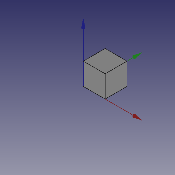
obj = my_box("test_cube", 5, 5, 5)
set_view()Write above lines of code after # Script functions and press the green arrow in the Macro toolbar.
You will see some magic things, a new document is open named \"Wiki_example\" and you will see in the 3d view a Cube, like the one in the image below.
Something more
Not that amazing? Yes, but we have to start somewhere, we can do the same thing with a Cylinder, add these lines of code after the my_box() function and before the line: # objects definition.
def my_cyl(name, ang, rad, hei):
    """Create a Cylinder."""
    obj = DOC.addObject("Part::Cylinder", name)
    obj.Angle = ang
    obj.Radius = rad
    obj.Height = hei

    DOC.recompute()

    return obj
Even here nothing too exciting. But please note some peculiarities:
- The absence of the usual reference to the
App., present in many Documentation code snippets, is deliberate, this code could be used even invoking FreeCAD as a module in an external Python interpreter, the thing is not easily doable with an AppImage, but with some care it could be done. Plus in the standard Python motto that \"better explicit than implicit\"App.is explaining in a very \"poor\" way where the things are from. - Note the use of the \"constant\" name assigned to the active Document in
DOC = FreeCAD.activeDocument(); activeDocument is not a \"constant\" in a strict sense, but in a \"semantical\" way is our \"active Document\", that for our use is a proper \"constant\" so the Python convention to use the \"ALL CAPS\" name for \"constants\", not to mention thatDOCis much shorten thanFreeCAD.activeDocument(). - Every function returns a geometry, this will be clear in the continuation of the page.
- Geometry didn\'t have the
Placementproperty, when using the simple geometries to make more complex geometry, managingPlacementis a awkward thing.
Now what to do with this geometries?
Let\'s introduce boolean operations. As a starter example put these lines after my_cyl, this create a function for a Fusion also know as Union operation:
def fuse_obj(name, obj_0, obj_1):
    """Fuse two objects."""
    obj = DOC.addObject("Part::Fuse", name)
    obj.Base = obj_0
    obj.Tool = obj_1
    obj.Refine = True
    DOC.recompute()

    return obj
Nothing exceptional also here, note however the uniformity in function coding; This approach is more linear than those seen around other tutorial on scripting, this \"linearity\" help greatly in readability and also with cut-copy-paste operations.
Let\'s use the geometries, delete lines below the code section starting with # objects definition, and insert the following lines:
# objects definition
obj = my_box("test_cube", 5, 5, 5)
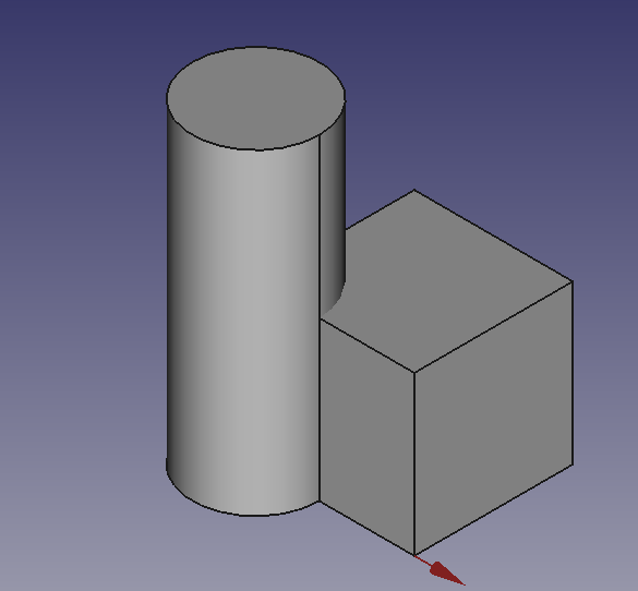
obj1 = my_cyl("test_cyl", 360, 2, 10)
fuse_obj("Fusion", obj, obj1)
set_view()Launch the script with the green arrow and we will see in the 3D view something like:
Placement
Placement Concept is relatively complex, see Aeroplane Tutorial for a more deep explanation.
We usually are in need of placing geometries respect each other, when building complex object this is a recurring task, the most common way is to use the geometry Placement property.
FreeCAD offer a wide choice of ways to set this property, one is more tailored to another depending the knowledge and the background of the user, but the more plain writing is explained in the cited Tutorial, it use a peculiar definition of the Rotation portion of Placement, quite easy to learn.
FreeCAD.Placement(Vector(0, 0, 0), FreeCAD.Rotation(10, 20, 30), Vector(0, 0, 0))But over other consideration, one thing is crucial, geometry reference point, in other words the point from which the object is modeled by FreeCAD, as described in this table, copied from Placement:
Object Reference Point
Part.Box left (minx), front (miny), bottom (minz) vertex Part.Sphere center of the sphere Part.Cylinder center of the bottom face Part.Cone center of bottom face (or apex if bottom radius is 0) Part.Torus center of the torus Features derived from Sketches the Feature inherits the Position of the underlying Sketch. Sketches always start with Position = (0, 0, 0). This position corresponds to the origin in the sketch.
This information has to be kept in mind especially when we have to apply a rotation.
Some examples may help, delete the my_box function and all lines after the my_cyl function, and add the code below after the my_cyl function:
def my_sphere(name, rad):
"""Create a Sphere."""
obj = DOC.addObject("Part::Sphere", name)
obj.Radius = rad
DOC.recompute()
return obj
def my_box2(name, len, wid, hei, cent=False, off_z=0):
"""Create a box with an optional z offset."""
obj_b = DOC.addObject("Part::Box", name)
obj_b.Length = len
obj_b.Width = wid
obj_b.Height = hei
if cent is True:
pos = Vector(len * -0.5, wid * -0.5, off_z)
else:
pos = Vector(0, 0, off_z)
obj_b.Placement = Placement(pos, ROT0, VEC0)
DOC.recompute()
return obj_b
def mfuse_obj(name, objs):
"""Fuse multiple objects."""
obj = DOC.addObject("Part::MultiFuse", name)
obj.Shapes = objs
obj.Refine = True
DOC.recompute()
return obj
def airplane():
"""Create an airplane shaped solid."""
fuselage_length = 30
fuselage_diameter = 5
wing_span = fuselage_length * 1.75
wing_width = 7.5
wing_thickness = 1.5
tail_height = fuselage_diameter * 3.0
tail_position = fuselage_length * 0.70
tail_offset = tail_position - (wing_width * 0.5)
obj1 = my_cyl("main_body", 360, fuselage_diameter, fuselage_length)
obj2 = my_box2("wings", wing_span, wing_thickness, wing_width, True, tail_offset)
obj3 = my_sphere("nose", fuselage_diameter)
obj3.Placement = Placement(Vector(0, 0, fuselage_length), ROT0, VEC0)
obj4 = my_box2("tail", wing_thickness, tail_height, wing_width, False, 0)
obj4.Placement = Placement(Vector(0, tail_height * -1, 0), ROT0, VEC0)
objs = (obj1, obj2, obj3, obj4)
obj = mfuse_obj("airplane", objs)
obj.Placement = Placement(VEC0, Rotation(0, 0, -90), Vector(0, 0, tail_position))
DOC.recompute()
return obj
# objects definition
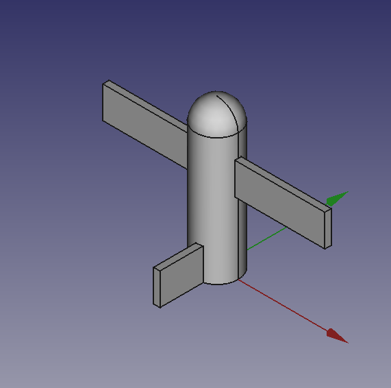
airplane()
set_view()
Let\'s explain something in the code:
- We have used a function to define a sphere, using the most easy definition, using only the radius.
- We have introduced a second writing for the Union or Fusion, using multiple objects, not more distant from the usual Part::Fuse it uses Part:Multifuse. We only use one property
Shapes. We have passed a tuple as arguments, but it accepts also a list. - We have defined a complex object airplane, but we have done it in a \"parametric\" way, defining some parameters and deriving other parameters, through some calculation, based on the main parameters.
- We have used some Placement
Placementpoperties around in the function and before returning the final geometries we have used aRotationproperty with the Yaw-Pitch-Roll writing. Note the lastVector(0, 0, tail_position), that define a center of rotation of the whole geometry.
++++
|  |
|  |
|  |
++++
|
++++
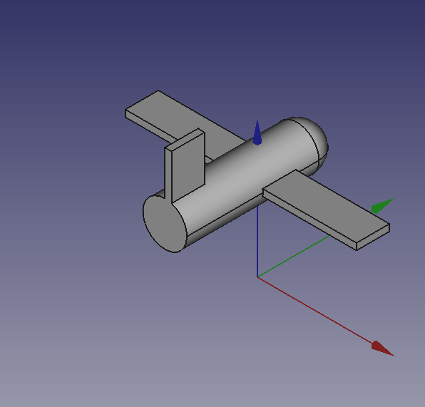
It can be easily noted that airplane geometry rotate around his \"barycenter\" or \"center of gravity\", that I\'ve fixed at wing center, a place that is relatively \"natural\", but could be placed wherever you want.
The first Vector(0, 0, 0) is the Translation vector, not used here, but if you substitute airplane() with these lines:
obj_f = airplane()
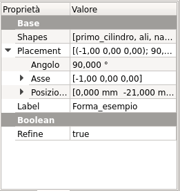
print(obj_F.Placement)You will see in the Report window this text:
Placement [Pos=(0, -21, 21), Yaw-Pitch-Roll=(0, 0, -90)]What has happened?
FreeCAD has translated the Vector(0, 0, 0), FreeCAD.Rotation(0, 0, -90), Vector(0, 0, tail_position) in other words our Placement definition that specifies three components, Translation, Rotation and center of rotation in the \"internal\" values of only two components, Translation and Rotation.
you can easily visualize the value of tail_position using a print statement in the airplane() function and see that it is:
tail_position = 21.0in other words the rotation center of the geometry is at Vector(0, 0, 21), but this rotation center is not shown in the GUI, it could be entered as a Placement value, it could not be easily retrieved.
This is the meaning of the word \"awkward\" that I\'ve used to define Placement property.
This is the complete code example with a decent script docstring following Google docstrings convention:
"""Sample code.

Filename:
   airplane.py

Author:
    Dormeletti Carlo (onekk)

Version:
    1.0

License:
    Creative Commons Attribution 3.0

Summary:
    This is sample code written for a FreeCAD Wiki page.
    It creates an airplane shaped solid using standard "Part WB" shapes.

"""

import FreeCAD
from FreeCAD import Placement, Rotation, Vector
import FreeCADGui

DOC_NAME = "Wiki_Example"
DOC = FreeCAD.newDocument(DOC_NAME)
FreeCAD.setActiveDocument(DOC.Name)

ROT0 = Rotation(0, 0, 0)
VEC0 = Vector(0, 0, 0)

# Helper function

def set_view():
    """Rearrange View."""
    if not FreeCAD.GuiUp:
        return
    doc = FreeCADGui.ActiveDocument
    if doc is None:
        return
    view = doc.ActiveView
    if view is None:
        return
    # Check if the view is a 3D view:
    if not hasattr(view, "getSceneGraph"):
        return
    view.viewAxometric()
    view.fitAll()

# Script functions

def my_cyl(name, ang, rad, hei):
    """Create a Cylinder."""
    obj = DOC.addObject("Part::Cylinder", name)
    obj.Angle = ang
    obj.Radius = rad
    obj.Height = hei

    DOC.recompute()

    return obj

def my_sphere(name, rad):
    """Create a Sphere."""
    obj = DOC.addObject("Part::Sphere", name)
    obj.Radius = rad

    DOC.recompute()

    return obj

def my_box2(name, len, wid, hei, cent=False, off_z=0):
    """Create a box with an optional z offset."""
    obj_b = DOC.addObject("Part::Box", name)
    obj_b.Length = len
    obj_b.Width = wid
    obj_b.Height = hei

    if cent is True:
        pos = Vector(len * -0.5, wid * -0.5, off_z)
    else:
        pos = Vector(0, 0, off_z)

    obj_b.Placement = Placement(pos, ROT0, VEC0)

    DOC.recompute()

    return obj_b

def mfuse_obj(name, objs):
    """Fuse multiple objects."""
    obj = DOC.addObject("Part::MultiFuse", name)
    obj.Shapes = objs
    obj.Refine = True
    DOC.recompute()

    return obj

def airplane():
    """Create an airplane shaped solid."""
    fuselage_length = 30
    fuselage_diameter = 5
    wing_span = fuselage_length * 1.75
    wing_width = 7.5
    wing_thickness = 1.5
    tail_height = fuselage_diameter * 3.0
    tail_position = fuselage_length * 0.70
    tail_offset = tail_position - (wing_width * 0.5)

    obj1 = my_cyl("main_body", 360, fuselage_diameter, fuselage_length)

    obj2 = my_box2("wings", wing_span, wing_thickness, wing_width, True, tail_offset)

    obj3 = my_sphere("nose", fuselage_diameter)
    obj3.Placement = Placement(Vector(0, 0, fuselage_length), ROT0, VEC0)

    obj4 = my_box2("tail", wing_thickness, tail_height, wing_width, False, 0)
    obj4.Placement = Placement(Vector(0, tail_height * -1, 0), ROT0, VEC0)

    objs = (obj1, obj2, obj3, obj4)

    obj = mfuse_obj("airplane", objs)
    obj.Placement = Placement(VEC0, Rotation(0, 0, -90), Vector(0, 0, tail_position))

    DOC.recompute()

    return obj

# objects definition

airplane()

set_view()
⏵ documentation index > Developer Documentation > Python Code > Scripts
This page is retrieved from https://github.com/FreeCAD/FreeCAD-documentation/blob/main/wiki/Scripts.md