Manual:Creating and manipulating geometry
In earlier chapters, we explored the various workbenches in FreeCAD and how each introduces its own set of tools and geometry types. The same principles apply when working with FreeCAD through Python scripting.
We also observed that most FreeCAD workbenches rely on one foundational workbench: the  Part Workbench. Many other workbenches, such as the
  Draft Workbench, utilize the Part Workbench\'s tools and geometry, which is exactly what we will do in this chapter---use Python to create and manipulate Part geometry.
To begin working with Part geometry in Python, we need to perform the scripting equivalent of switching to the Part Workbench: importing the Part module.
import Part Take a moment to explore the Part module by typing Part. in the Python console and browsing through the available methods and attributes in the autocomplete window. This is a great way to familiarize yourself with the functionality the module offers. You\'ll find a variety of convenient functions, such as makeBox and makeCircle, which allow you to quickly create geometric shapes and objects with just a single command. Many of these functions also offer optional parameters, giving you precise control over dimensions and placement.
Spending some time browsing the module's contents not only helps you understand what tools are at your disposal but also gives you insight into how the Part Workbench operates under the hood. This foundational knowledge will prove invaluable as we move forward and begin creating and manipulating geometry programmatically. Type the following command
Part.makeBox(3,5,7) This command creates a 3D box, also known as a rectangular prism, with specific dimensions. The first parameter, 3, defines the length of the box along the X-axis. The second parameter, 5, sets the width along the Y-axis, and the third parameter, 7, specifies the height along the Z-axis. While this function generates the geometry of the box, it does not automatically add it to the active FreeCAD document. In the Python console you will see the following:
<Solid object at 0x5f43600> The output \<Solid object at 0x5f43600> indicates that a Part Shape has been created in memory. This is a geometric object stored at a specific memory address, as shown by the hexadecimal value (0x5f43600). However, it is important to understand that what we created here is not yet a FreeCAD document object---it exists only as a raw geometric shape in memory.
This distinction highlights a fundamental concept in FreeCAD: objects and their geometry are independent. A FreeCAD document object serves as a container that hosts a shape. These document objects can have additional properties, such as Length, Width, and Height, and they can be parametric. Parametric objects recalculate their geometry (or shape) dynamically whenever one of their properties changes. For instance, modifying the length of a parametric box will automatically regenerate its shape with the updated value.
In this case, we manually created a shape using the Part.makeBox() function. This shape is a non-parametric object, meaning it won't update automatically based on any properties---it is static unless we manipulate it programmatically. To make this shape part of the active FreeCAD document, it would need to be assigned to a document object (like a Part::Feature), which would link it to the graphical interface and make it visible and manageable within the FreeCAD environment.
This separation between shapes and document objects is what makes FreeCAD highly versatile, allowing users to manipulate shapes programmatically and integrate them into a parametric modeling workflow as needed.
We can now easily create a \"generic\" document object in the current document (make sure you have at least one new document open), and give it a box shape like the one we just made:
boxShape = Part.makeBox(3,5,7)
myObj = FreeCAD.ActiveDocument.addObject("Part::Feature","MyNewBox")
myObj.Shape = boxShape
FreeCAD.ActiveDocument.recompute()
Here is a breakdown of the previous commands:
-
boxShape = Part.makeBox(3,5,7): Creates a 3D box with dimensions 3x5x7 (length, width, and height) and stores it as a Part Shape in the variable boxShape. This shape exists only in memory and is not yet part of the FreeCAD document.
-
myObj = FreeCAD.ActiveDocument.addObject(\"Part::Feature\", \"MyNewBox\"): Adds a new Part::Feature object named \"MyNewBox\" to the active FreeCAD document and assigns it to the variable myObj. The new object will appear in the FreeCAD document tree.
-
myObj.Shape = boxShape: Links the boxShape geometry to the Shape property of myObj, integrating the geometry into the FreeCAD document.
-
FreeCAD.ActiveDocument.recompute(): Updates the document to reflect the changes, ensuring that the new object and its geometry appear in the graphical interface.
Note how we handled myObj.Shape. It was done in the same way as in the previous chapter, where we changed other properties of an object, such as box.Height = 5. In fact, Shape is also a property, just like Height. However, instead of taking a number, Shape requires a Part Shape. In the next chapter, we will take a closer look at how these parametric objects are constructed.
For now, let\'s explore Part Shapes in more detail. In the chapter on traditional modeling with the Part Workbench, we introduced a table explaining how Part Shapes are constructed and the different components they consist of, such as vertexes, edges, and faces. These same components are available when working with Part Shapes in Python, allowing for detailed exploration and manipulation of geometry. Part Shapes in FreeCAD always have the following attributes:
- Vertexes: Points in 3D space that define the corners or endpoints of geometry.
- Edges: Straight or curved lines connecting two vertexes.
- Wires: Closed or open loops formed by one or more connected edges.
- Faces: Surfaces enclosed by one or more wires.
- Shells: Groups of connected faces, forming a continuous surface.
- Solids: 3D volumes enclosed by one or more shells.
All of these attributes are represented as lists in Python. Each list can contain any number of elements or be empty, depending on the shape being explored. For example, a box will have eight Vertexes, twelve Edges, six Faces, one Shell, and one Solid, while a line will only have two Vertexes and one Edge, with all other attributes being empty. These components are fundamental building blocks of Part geometry and can be accessed and manipulated programmatically. Understanding how they interact provides powerful control over the creation and modification of 3D models. We can access those lists as follows:
print(boxShape.Vertexes)
print(boxShape.Edges)
print(boxShape.Wires)
print(boxShape.Faces)
print(boxShape.Shells)
print(boxShape.Solids)
Let\'s find the area of each face of our box shape above: (Make sure to indent the second line, as it appears below. Press Enter twice after the last line to run the Python command.)
for f in boxShape.Faces:
   print(f.Area)
Or, for each edge, its start point and end point:
for e in boxShape.Edges:
   print("New edge")
   print("Start point:")
   print(e.Vertexes[0].Point)
   print("End point:")
   print(e.Vertexes[1].Point)
As you see, if our boxShape has a \"Vertexes\" attribute, each Edge of the boxShape also has a \"Vertexes\" attribute. As we can expect, the boxShape will have 8 vertices, while the edge will only have 2, which are both parts of the list of 8.
We can always check what is the type of a shape:
print(boxShape.ShapeType)
print(boxShape.Faces[0].ShapeType)
print(boxShape.Vertexes[2].ShapeType)
Here is a short explanation of the above commands:
-
print(boxShape.ShapeType): Displays the type of the top-level shape represented by boxShape. In this case, since boxShape was created as a box using Part.makeBox, the output will be \"Solid\", indicating that the shape is a 3D solid object.
-
print(boxShape.Faces[0].ShapeType): Accesses the first face in the Faces list of boxShape (index 0) and prints its shape type. For a box, each face is a flat surface, so the output will be \"Face\".
-
print(boxShape.Vertexes[2].ShapeType): Accesses the third vertex in the Vertexes list of boxShape (index 2) and prints its shape type. Since this is a specific point in 3D space, the output will be \"Vertex\".
To summarize the concept of Part Shapes: Everything begins with Vertexes, the most basic elements of geometry. Using one or two Vertexes, you can create an Edge (note that full circles require only one Vertex). One or more Edges can then form a Wire, which can be either open or closed. When you have one or more closed Wires, you can create a Face. Additional Wires inside the main Wire will act as \"holes\" in the Face. Combining one or more Faces allows you to construct a Shell, which is essentially a collection of connected surfaces. If a Shell is fully closed and watertight, it can then be used to form a Solid---a 3D object with volume. Finally, any number of shapes of any type, including Vertexes, Edges, Wires, Faces, Shells, or Solids, can be grouped together into a Compound, which acts as a container for multiple shapes.
We can now try creating complex shapes from scratch, by constructing all their components one by one. For example, let\'s try to create a volume like this:

We will start by creating a planar shape like this:
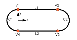
First, let\'s create the four base points:
V1 = FreeCAD.Vector(0,10,0)
V2 = FreeCAD.Vector(30,10,0)
V3 = FreeCAD.Vector(30,-10,0)
V4 = FreeCAD.Vector(0,-10,0)
Then we can create the two linear segments:
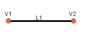
L1 = Part.LineSegment(V1,V2)
L2 = Part.LineSegment(V4,V3)
Note that we didn't need to create Vertexes explicitly. Instead, we could directly create Part.LineSegments using FreeCAD Vectors. This is because at this stage, we are working with base geometry, not actual Edges. A Part.LineSegment, as well as Part.Circle, Part.Arc, Part.Ellipse, or Part.BSpline, defines the underlying geometry but does not generate an edge by itself. In FreeCAD, edges are always constructed from such base geometry, which is stored in the Curve attribute of the Edge. This means that an edge is essentially a wrapper around the base geometry, inheriting its properties. If you have an edge, you can access its underlying geometry by referring to the curve attribute. The following command:
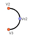
print(Edge.Curve) allows you to understand the underlying structure of the edge and how it was constructed. Now, let's return to our exercise and proceed with building the arc segments. To create an arc, we need three points: a start point, an end point, and a midpoint that determines the curvature. For this purpose, we can use the convenient Part.Arc function, which takes these three points as input and generates the base geometry for an arc.
VC1 = FreeCAD.Vector(-10,0,0)
C1 = Part.Arc(V1,VC1,V4)
VC2 = FreeCAD.Vector(40,0,0)
C2 = Part.Arc(V2,VC2,V3)
Now we have 2 lines (L1 and L2) and 2 arcs (C1 and C2). We need to turn them into edges:
E1 = Part.Edge(L1)
E2 = Part.Edge(L2)
E3 = Part.Edge(C1)
E4 = Part.Edge(C2)
Alternatively, base geometries also have a toShape() function that does exactly the same thing:
E1 = L1.toShape()
E2 = L2.toShape()
 ...
Once we have a series of edges, we can now form a Wire, by giving it a list of edges. We do need to pay attention to the order. Also, note the brackets.
W = Part.Wire([E1,E4,E2,E3]) And we can check if our wire was correctly understood, and that it is correctly closed:
print( W.isClosed() ) Which will print \"True\" or \"False\". In order to make a Face, we need closed Wires, so it is always a good idea to check that before creating the face. Now we can create a face, by giving it a single wire (or a list of wires if we want holes):
F = Part.Face(W) Then we extrude it:
P = F.extrude(FreeCAD.Vector(0,0,10)) Note that P is already a Solid:
print(P.ShapeType) This is because when we extrude a single face, we always get a solid. This wouldn\'t be the case, for example, if we had extruded the wire instead:
S = W.extrude(FreeCAD.Vector(0,0,10))
print(S.ShapeType)
Which will of course give us a hollow shell, with the top and bottom faces missing.
Now that we have our final Shape, we are anxious to see it on screen! So let\'s create a generic object, and assign our new Solid to it:
myObj2 = FreeCAD.ActiveDocument.addObject("Part::Feature","My_Strange_Solid")
myObj2.Shape = P
FreeCAD.ActiveDocument.recompute()
Alternatively, the Part module also provides a shortcut that does the above operation quicker (but you cannot choose the name of the object):
Part.show(P) All of the above, and much more, is explained in detail on the Part Scripting page, together with examples.
Read more:
⏵ documentation index > Developer Documentation > Python Code > Manual:Creating and manipulating geometry
This page is retrieved from https://github.com/FreeCAD/FreeCAD-documentation/blob/main/wiki/Manual_Creating_and_manipulating_geometry.md