Introduction
The preferences for the ![]() Sketcher Workbench can be found in the Preferences Editor. In the menu select Edit → Preferences and then
Sketcher Workbench can be found in the Preferences Editor. In the menu select Edit → Preferences and then ![]() Sketcher. This group is only available if the Sketcher Workbench has been loaded in the current FreeCAD session.
Sketcher. This group is only available if the Sketcher Workbench has been loaded in the current FreeCAD session.
There are four pages: General, Grid, Display and Appearance.
Some advanced preferences can only be changed in the Parameter editor. See Fine-tuning.
In 0.21 and below the Appearance page is labeled "Colors".
General
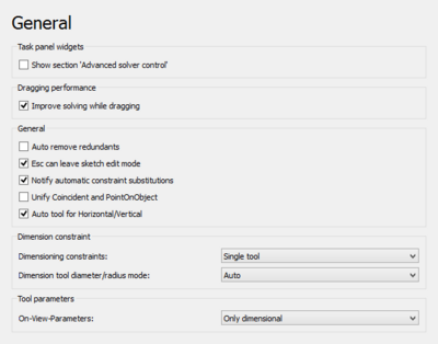
On this page you can specify the following:
| Name | Description |
|---|---|
| Show section 'Advanced Solver Controls' | If checked, the sketcher dialog will show the section Advanced Solver Controls to adjust solver settings. |
| Improve solving while dragging | If checked, a special solver algorithm will be used while dragging sketch elements. This avoids that the sketch flips around while dragging. It is an improvement for most cases, however for complex sketches this option can increase the time to solve the sketch. |
| Auto remove redundant constraints | If checked, new constraints that are redundant are automatically removed. |
| Esc key can leave sketch edit mode | If checked, the Esc key can trigger exiting sketch edit mode. The option to disable this may be useful for users who are used to pressing Esc as part of their workflow in other CAD solutions but don't necessarily want to exit a sketch. |
| Disable shading in edit mode Only available in introduced in 1.0. | If checked, the shaded view is disabled when entering sketch edit mode. |
| Notify about automatic constraint substitutions | If checked, you will be informed with a dialog about constraint substitutions. For example if the endpoints of two arcs are connected with the coincident constraint and you reconnect the arcs using the tangent constraint, the coincidence constraint will be substituted by the tangent constraint and you will get a popup dialog telling you this. |
| Unify coincident and point-on-object constraints introduced in 1.0 | If checked, the coincident constraint tool and point-on-object constraint tool are unified in a single tool.
After changing this preference you must restart FreeCAD. |
| Unified tool for automatic horizontal/vertical constraints introduced in 1.0 | If checked, the automatic horizontal/vertical constraint tool is added to the toolbar (it is always available in the menu and through its shortcut), and the horizontal constraint tool and vertical constraint tool are grouped below it in a dropdown.
After changing this preference you must restart FreeCAD. |
| Group the polyline and line commands introduced in 1.1 | If checked, a command group button that contains both the polyline and line commands is shown. Otherwise, each command has its own separate button.
After changing this preference you must restart FreeCAD. |
| Always add external geometry as construction introduced in 1.1 | If checked, external geometry is always added as construction geometry regardless of the current construction mode. |
| Generate internal faces introduced in 1.1 | If checked, closed loops will automatically generate internal faces which are selectable to be used with other tools. |
| Dimensioning constraints introduced in 1.0 | Specifies the dimensional constraint tools for the toolbar (all dimensional tools are always available in the menu and through their shortcuts). The options are:
After changing this preference you must restart FreeCAD. |
| Dimension tool diameter/radius mode introduced in 1.0 | Specifies how the combined Dimension tool handles circles and arcs. Disabled if the previous preference is set to Separated tools. The options are:
|
| Scale upon first constraint introduced in 1.1 | Specifies how automatic geometry scaling upon first dimension is performed:
|
| On-view-parameters (OVP) introduced in 1.0 | Specifies the visibility mode for the On-view-parameters. The options are:
|
Grid
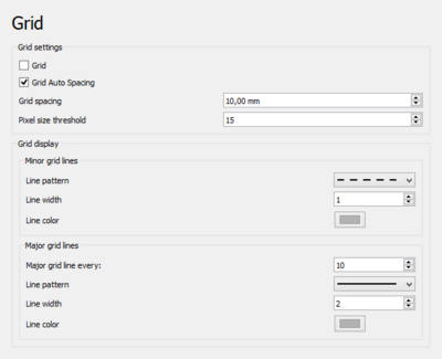
On this page you can specify the following:
| Name | Description |
|---|---|
| Grid | If checked, a grid will be shown while the sketch is in edit mode. Used for new sketches. Is stored in the VistaShow Grid property of sketches. |
| Grid auto-spacing | If checked, grid spacing is automatically adapted based on the view dimensions. Used for new sketches. Is stored in the VistaGrid Auto property of sketches. |
| Grid spacing | The distance between two subsequent grid lines. Used as a base value if Grid auto-spacing is enabled. Used for new sketches. Is stored in the VistaGrid Size property of sketches. |
| Pixel size threshold | The grid spacing threshold in pixels. Only used if Grid auto-spacing is enabled. If the onscreen spacing is smaller than this value, physical grid spacing is multiplied by the Major grid line interval value. If the onscreen spacing is larger than the threshold value times the interval value, physical grid spacing is divided by the interval value. If the interval value is set to 1, 10 is used instead in these calculations. |
| Minor Grid Lines | For minor grid lines you can specify:
|
| Major Grid Lines | For major grid lines you can specify:
|
| Grid transparency introduced in 1.2 | Sets the transparency of the grid displayed while a sketch is in edit mode. Used for new sketches. |
Display
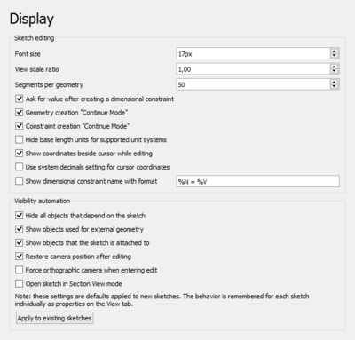
On this page you can specify the following:
| Name | Description |
|---|---|
| Font size | The font size used for the labels and constraints in the sketch. |
| Constraint symbol size introduced in 1.1 | Pixel size for constraint symbols. |
| View scale ratio introduced in 0.21 | The 3D View is scaled based on this factor. |
| Segments per geometry | Curves are approximated by polygon segments for visualization. This value defines the number of segments. The lower limit is 50 segments. Higher values refine the visualization but can lead to longer calculation times, especially for B-splines. |
| Ask for value after creating a dimensional constraint | If checked, a dialog will pop up to input a value for new dimensional constraints. |
| Geometry creation "Continue Mode" | If checked, geometry creation tools will remain active after creating an element. You can leave a tool any time by right-clicking in the sketch. |
| Constraint creation "Continue Mode" | If checked, constraint creation tools will remain active after creating a constraint. You can leave a tool any time by right-clicking in the sketch. |
| Hide base length units for supported unit systems | If checked, the length unit from the selected unit system is used but not displayed in sketch constraints. Only for supported unit systems. |
| Show coordinates next to the cursor while editing introduced in 0.21 | If checked, cursor coordinates are displayed beside the cursor while editing a sketch. |
| Use system decimals setting for cursor coordinates introduced in 0.21 | If checked, cursor coordinates will use the system decimals setting instead of the short form. |
| Show dimensional constraint name with format introduced in 0.21 | If checked, the names of dimensional constraints (if available) are displayed using the given format:
|
| Hide all objects that depend on the sketch | If checked, all objects that depend on the sketch will be hidden when the sketch is opened. Note that this may have no effect if the Show objects used for external geometry and/or Show objects that the sketch is attached to options are selected. |
| Show objects used for external geometry | If checked, hidden objects used for external geometry will be shown when the sketch is opened. |
| Show objects that the sketch is attached to | If checked, hidden objects the sketch is attached to will be shown when the sketch is opened. |
| Restore camera position after editing | If checked, the camera position is moved back to where it was before the sketch was opened. |
| Force orthographic camera when entering edit | If checked, camera mode will be forced to orthographic when the sketch is opened. Camera mode will be restored when leaving edit mode. This preference is only available if Restore camera position after editing is activated. |
| Open sketch in section view mode | If checked, the sketch will open with 'Section View' active. |
| Apply to Existing Sketches | If pressed, the Visibility Automation settings will be applied to existing sketches too. Otherwise they will only be used for new sketches. |
Appearance
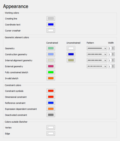
Unless otherwise stated these preferences are only used while a sketch is in edit mode.
On this page you can specify the following:
| Name | Description |
|---|---|
| Creating line | The color used for sketch elements while they are being created. |
| Coordinate text | The color used for the coordinates displayed while creating sketch elements. |
| Cursor crosshair | The color used for the crosshair cursor displayed while creating sketch elements. |
| Geometry introduced in 1.0 | The colors used for constrained and unconstrained normal geometry. The line pattern and line width can also be specified. |
| Construction geometry | The colors used for constrained and unconstrained construction geometry. introduced in 1.0: The line pattern and line width can also be specified. |
| Internal alignment geometry | The colors used for constrained and unconstrained internal alignment geometry. introduced in 1.0: The line pattern and line width can also be specified. |
| External construction geometry introduced in 1.1 | The color used for external construction geometry. The line pattern and line width can also be specified. |
| External defining geometry introduced in 1.1 | The color used for external defining geometry. The line pattern and line width can also be specified. |
| Fully constrained sketch | The color used for a fully constrained sketch. |
| Invalid sketch | The color used for an invalid sketch. |
| Constraint symbols | The color used for driving geometric constraints. |
| Dimensional constraint | The color used for driving dimensional constraints. |
| Reference constraint | The color used for reference dimensional constraints. |
| Expression dependent constraint | The color used for expression dependent dimensional constraints. |
| Deactivated constraint | The color used for deactivated constraints. |
| Colors Outside Sketcher: Vertex | The color used for vertices (points) when not in edit mode. |
| Colors Outside Sketcher: Edge | The color used for edges when not in edit mode. |
| Colors Outside Sketcher: Face | The color used for internal faces formed by intersection geometry or closed loops when not in edit mode. |
The colors for selections while a sketch is in edit mode are controlled by the global settings Enable preselection and Enable selection, see the Preferences Editor.
The size of the vertices in edit mode is controlled by the Marker size setting.
Note
There is another preference that has an influence on sketches. If the Transparent objects preference on the Display → 3D View tab is set to Backface pass, arrowheads on one end of sketch dimensions are hidden on some systems. When viewed from the rear the dimension value can then also be hidden. Versions 0.19 to 0.21 (except Link branch) are affected. In versions 0.19 and 0.20 the effect only occurs if Display grid is deactivated in the Edit controls section of the Task panel as shown below.
See forum topic.
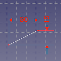
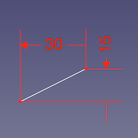
Front view, grid enabled and grid disabled
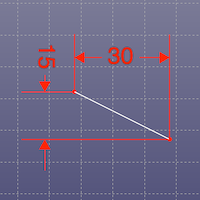
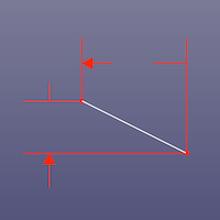
Rear view, grid enabled and grid disabled hiding arrowheads on the opposite end as well as the dimension value
Esta página ha sido recuperada de https://wiki.freecad.org/Sketcher_Preferences